
Page 278 - Power Electronics Handbook
P. 278
268 D.C. to d.c. converters
12.2.3.1 High-frequency operation
Two problems can arise when a chopper is operated at high frequencies.
First, the finite time required to set and reset the commutation capacitor
limits the maximum and minimum voltage at any frequency. Second, the
necessity of ensuring that a thyristor is reverse biased for the duration of its
turn-off time limits the operating frequency unless some form of
sequencing is used, as explained later.
In the circuit shown in Figure 12.4 suppose that C is charged to V, with
plate b positive, due to a preceding cycle. Thyristor TH1 is now fired to
supply the load current and simultaneously TH3 is turned on to cause C to
resonate through L1 and to recharge with plate a positive. The resonant
time is given by equation (12.4) and represents the minimum on period for
THl, since TH2 cannot be turned on to commutate it until the capacitor has
been set.
tc = ~J(w9 (12.4)
When TH2 is fired thyristor TH1 turns off and C discharges at constant
(assumed) load current ZL, recharging to V, in a time given by equation (12.5).
2c v,
r, = - (12.5)
IL
Thyristor TH1 cannot be refired until this is completed, therefore it
represents its minimum off period. Capacitor C is chosen to ensure that
THI is reverse biased for longer than its turn-off time, under maximum
load conditions. If the load current now falls, the reset time can be very
large, severely limiting the peak output voltage.
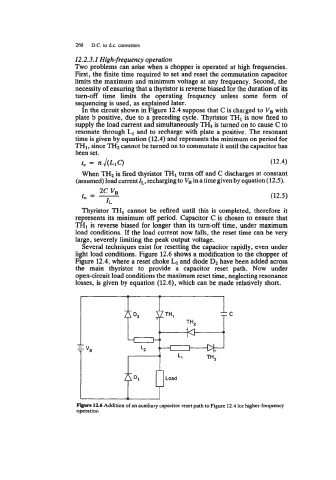
Several techniques exist for resetting the capacitor rapidly, even under
light load conditions. Figure 12.6 shows a modification to the chopper of
Figure 12.4, where a reset choke LZ and diode D2 have been added across
the main thyristor to provide a capacitor reset path. Now under
open-circuit load conditions the maximum reset time, neglecting resonance
losses, is given by equation (12.6), which can be made relatively short.
Figure 12.6 Addition of an auxiliary capacitor reset path to Figure 12.4 for higher-frequency
operation