
Page 275 - Power Electronics Handbook
P. 275
D.C. to d.c. converter circuits 265
circuits, for high-power applications thyristors are still the main switching
component, these devices requiring forced commutation when operating
from a d.c. supply. The various chopper commutation circuits were
introduced in Chapter 11, as illustrations for the forced commutation
classification system. A few further commutation circuits are described in
this section.
"6 -
Load
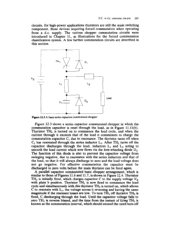
Fiyre 12.3 A basic series capacitor commutated chopper
Figure 12.3 shows a series capacitor commutated chopper in which the
commutation capacitor is reset through the load, as in Figure ll.ll(b).
Thyristor TH1 is turned on to commence the load cycle, and when the
current through it exceeds that of the load it commences to charge the
commutation capacitor C1 due to resonance. The thyristor turns off when
C1 has resonated through the series inductor L1. After TH1 turns off the
capacitor discharges through the load, inductors L1 and L2 acting to
smooth the load current which now flows via the free-wheeling diode D2.
The function of this diode is also to prevent the capacitor voltage from
swinging negative, due to resonance with the series inductors and that of
the load, so that it will always discharge to zero and the load voltage does
not go negative. For effective commutation the capacitor must be
discharged to zero volts before the main thyristor can be fired again.
A parallel capacitor commutated basic chopper arrangement, which is
similar to those of Figures 11.6 and 11.7, is shown in Figure 12.4. Thyristor
TH2 is initially fired, which charges capacitor C to the supply voltage V,
with plate b positive. Thyristor TH1 is now fired to commence the load
cycle and simultaneously with this thyristor TH3 is turned on, which allows
C to resonate with L1, the voltage across it reversing and having the same
magnitude if the resonant losses are low. To turn TH1 off thyristor TH2 is
fired, C discharging through the load. Until the capacitor voltage falls to
zero TH1 is reverse biased, and the time from the instant of fhing TH2 is
known as the commutation interval, which should exceed the rated turn-off