
Page 272 - Power Electronics Handbook
P. 272
262 D.C. to d.c. converters
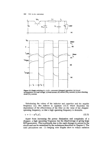
Figure 12.1 Bask switching d.c. to d.c. converter (chopper) operation: (a) circuit
arrangement; (b) load voltage; (c) load current; (d) switch (TRI) current; (e) freewheeling
diode (D,) current
Substituting the values of the inductor and capacitor and the angular
frequency (o), this reduces to equation (12.3) which illustrates the
dependence of the effectiveness of the filter on the value of the chopper-
operating frequency, so that a high operating frequency is desirable.
T = 1 - 02LIC1 (12.3)
Apart from increasing the power dissipation and complexity of a
chopper, a high operating frequency has the disadvantage of giving large
RFI generation. This is primarily due to the rapid changes in current in the
circuit and can be minimised by the techniques described in Chapter 4. The
main precautions are: (1) keeping wire lengths short to reduce radiation