
Page 268 - Power Electronics Handbook
P. 268
258 Forced commutation techniques
Series capacitor commutation circuits have a very limited operational
range, due to the capacitor reset time, and are rarely used as choppers.
They find more frequent application as sine wave inverters, and this will be
discussed further in Chapter 13.
11.6 Coupled-pulse commutation
The elementary coupled circuit shown in Figure 11.2(d) used a transformer
to couple the charge from the commutation capacitor onto the conducting
thyristor, reverse biasing it and turning it off. The auxiliary circuitry for
priming the commutation capacitor is not shown, but since an isolating
transformer is employed this can consist of a variety of systems, In
addition, the capacitor can be replaced by a separate d.c. source, which is
momentarily coupled onto the main thyristor using a power semiconduc-
tor. Such a device could be a transistor or gate turn-off switch, which can
be turned off by means of signals on its control terminal, the transformer
being used to match the voltage and current rating of the device to that of
the load.
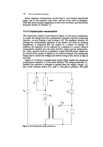
Figure 11.12 shows a coupled-pulse circuit which couples the charge on
commutation capacitor C to the main thyristor TH1 using transformer T1.
Initially the capacitor is charged to greater than the supply voltage, V,,
due to the resonant action of L1 and C, with plate b positive. The main
F@ue 11.12 Coupled pulse ushg a transformer