
Page 263 - Power Electronics Handbook
P. 263
Parallel capacitor-inductor commutation 253
with plate b positive before the main thyristor is fired to commence the
load cycle. When TH1 is fired the voltage of this charged capacitor is
placed across reactor L1. The reactor blocks the voltage for a time tp
required to drive it into positive saturation. When this has occurred the
reactor presents an after-saturation inductance L1 to the capacitor and it
resonates, recharging with plate a positive. Once resonance has been
completed the reactor comes out of saturation and blocks current. It is now
driven into negative saturation by the reversed capacitor voltage and after
a negative saturation time t,, it again reaches saturation and capacitor C
commences its discharge through the load (ignoring the effect of diode D2
for the present), turning off the main thyristor THI.
The diode D2 across the main thyristor is optional, and it could have
been added to the circuit of Figure 11.8 as well, if required. It provides a
path for the capacitor discharge current when the load current is very low.
Therefore on an open-circuit load the capacitor would resonate through L1
and D,.
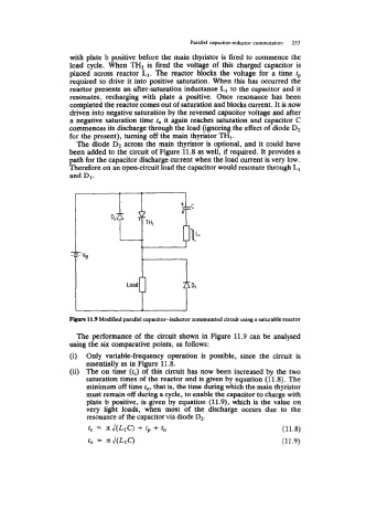
F m 11.9 Modified parallel capacitor-inductor commutated circuit using a saturable reactor
The performance of the circuit shown in Figure 11.9 can be analysed
using the six comparative points, as follows:
(i) Only variable-frequency operation is possible, since the circuit is
essentially as in Figure 11.8.
(ii) The on time (tc) of this circuit has now been increased by the two
saturation times of the reactor and is given by equation (11.8). The
minimum off time to, that is, the time during which the main thyristor
must remain off during a cycle, to enable the capacitor to charge with
plate b positive, is given by equation (11.9), which is the value on
very light loads, when most of the discharge occurs due to the
resonance of the capacitor via diode D2.
tc = nJ(L1C) + fp + t" (11.8)
to = Jc J(L*c) (11.9)