
Page 260 - Power Electronics Handbook
P. 260
250 Forced commutation techniques
auxiliary thyristor TH2 also turns off, so that there is negligible quiescent
power loss in the circuit.
The circuit of Figure 11.6 can be analysed using the six points discussed
earlier, as follows:
(i) Both variable-frequency and variable mark-space operational modes
are possible.
(ii) The same comments regarding minimum on and off times, made
when discussing Figure 11.5, apply here.
(iii) The commutation voltage is not boosted by load current.
(iv) If thyristor TH2 is fired to commence the commutation cycle of the
main thyristor TH1 (plate a of the capacitor being positive) and
commutation is unsuccessful, i.e. TH1 fails to turn off, then the
commutation capacitor C will discharge to zero and TH2 will turn off.
Since THI is still conducting, C cannot recharge to V, so
commutation will not be re-attempted. ‘Once-for-all’ commutation
failure has occurred and the chopper can only be restarted by first
breaking the supply to THl, rendering it non-conducting, and then
re-applying the supply.
(v) The rating of the main thyristor THI is increased by the resonant
capacitor charge.
(vi) A low-impedance failure path does not exist across the supply
voltage, assuming that diode Dl has not failed to a short circuit.
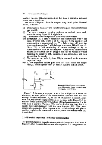
Figure 11.7 Modification to Figure 11.6
to avoid capacitor charge current flowing
through the main thyristor
Figure 11.7 shows an alternative circuit to that in Figure 11.6, where the
discharge resonant pulse of the commutation capacitor does not flow
through the main thyristor TH1, so that its rating is not increased. Apart
from this, the circuit design parameters are the same as for Figure 11.6. At
the start of the cycle thyristor TH2 is fired which charges capacitor C to VB
with plate b positive. Thyristor TH3 can be fired at any time, but it is
usually fired simultaneously with the main thyristor THI. This causes
commutation capacitor C to resonate with L1 and recharge with plate a
positive, ready for the commutation interval, which commences when TH2
is next fired.
11.4 Parallel capacitor-inductor commutation
The parallel capacitor-inductor commutation technique was introduced in
Figure 11.2(b). Assume that commutation capacitor C is charged with the