
Page 262 - Power Electronics Handbook
P. 262
252 Forced commutation techniques
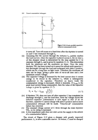
Figure 11.8 A basic parallel capacitor-
inductor commutated circuit
it turns off. Turn-off occurs at a fixed time after the thyristor is turned
on and C has resonated through L1.
(ii) Assuming that the current through the inductor L1 quickly reaches
the load current, when the capacitor is placed across it, the on time tc
of this chopper circuit is determined by the time needed for C to
resonate through L1 and is given by equation (11.3). This determines
both the minimum and the maximum on times. Once the main
thyristor TH1 has been turned on it cannot be refired until capacitor C
has discharged through the load and recharged with plate b positive,
which can be a long time on light loads. Therefore the minimum off
time can be large, giving a poor ratio of on-to-off time and a low
maximum output voltage.
(iii) The capacitor voltage is increased by the load current since it cause.s
energy to be stored in the inductor L1 which is subsequently
transferred to the capacitor. Therefore on heavy loads the
commutation energy is increased, which is desirable. If lL(pk) is the
peak load current being commutated, then the value of the capacitor
voltage is given by equation (1 1.7).
(11.7)
(iv) If thyristor TH1 does not turn off after capacitor C has completed its
discharge through L1 and the load then, since the voltage across the
inductor-capacitor commutation is now equal to that of an on
thyristor, capacitor C cannot charge with plate b positive and no more
commutation attempts will be made. ‘Once-for-all’ commutation
failure has occurred.
(v) The resonant charge current of C flows through the main thyristor
THl, so its rating is increased.
(vi) A low-impedance path does not exist &cross the supply in the advent
of a commutation failure.
The circuit of Figure 11.9 gives a chopper with greatly improved
performance. L1 is now a saturable reactor. As before, C must be charged