
Page 259 - Power Electronics Handbook
P. 259
Parallel-capacitor commutation 249
is desired not to refire TH1 until C has completed its charge through
THz, and this determines the maximum output load voltage from this
chopper circuit. This situation is common to all systems where the
turn-off pulse flows through the load.
(iii) The commutation voltage is determined by the resonant circuit and is
not increased by the load voltage if the inductances of the leads are
ignored.
(iv) If the main thyristor TH1 fails to turn off during a commutation
attempt, when THz is fired, then when TH3 is next fired it will again
recharge C ready for another commutation attempt, which will be
successful if the load current has reduced.
(v) The rating of the main thyristor TH1 has been increased by the
charging pulse required for capacitor C, via TH3. This is also true for
the circuit of Figure 11.3, although it is avoided in the circuit of
Figure 11.4, where the charging current contributes to the load
current.
(vi) A fault condition, which resulted in both thyristors TH3 and TH,
being gated on simultaneously, would give a low-impedance path
across the supply, which would destroy both devices unless they were
protected by fuses.
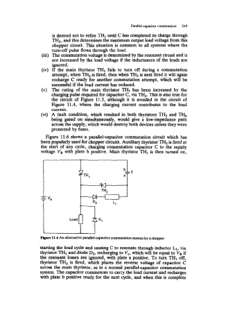
Figure 11.6 shows a parallel-capacitor commutation circuit which has
been popularly used for chopper circuits. Auxiliary thyristor TH2 is fired at
the start of any cycle, charging commutation capacitor C to the supply
,
voltage VB with plate b positive. Main thyristor THI is then turned on,
pirve 11.6 An alternative parallel-capacitor commutation system for a chopper
starting the load cycle and causing C to resonate through inductor L1, via
thyristor TH1 and diode D2, recharging to V,, which will be equal to VB if
the resonant losses are ignored, with plate a positive. To turn TH1 off,
thyristor TH2 is fired, which places the reverse voltage of capacitor C
across the main thyristor, as in a normal parallel-capacitor commutation
system. The capacitor commences to carry the load current and recharges
with plate b positive ready for the next cycle, and when this is complete