
Page 256 - Power Electronics Handbook
P. 256
246 Forced commutation techniques
and recharging again from the battery, with a polarity opposite to that
shown in Figure 11.2. This is given by equation (1 1.2) and its value must be
less than the dv/dt rating of the thyristor for it to remain off after the
commutation (reverse bias) period.
(11.2)
Equations (1 1.1) and (1 1.2) are applicable to all parallel-capacitor
commutated circuits and enable the correct capacitor value to be chosen
for a given load and device characteristic. The magnitude of the capacitor
voltage (Vc), just prior to the start of commutation, will depend on the
auxiliary circuit used to prime the capacitor.
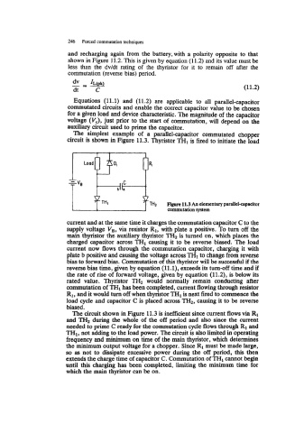
The simplest example of a parallel-capacitor commutated chopper
circuit is shown in Figure 11.3. Thyristor TH1 is fired to initiate the load
Load
--
+ Vs ,IC <
bllo
TH2 Figure 11.3 An elementary parallelcapacitor
commutation system
current and at the same time it charges the commutation capacitor C to the
supply voltage V,, via resistor R1, with plate a positive. To turn off the
main thyristor the auxiliary thyristor TH2 is turned on, which places the
charged capacitor across THI causing it to be reverse biased. The load
current now flows through the commutation capacitor, charging it with
plate b positive and causing the voltage across THl to change from reverse
bias to forward bias. Commutation of this thyristor will be successful if the
reverse bias time, given by equation (ll.l), exceeds its turn-off time and if
the rate of rise of forward voltage, given by equation (11.2), is below its
rated value. Thyristor TH2 would normally remain conducting after
commutation of TH1 has been completed, current flowing through resistor
R1, and it would tun off when thyristor TH1 next fired to commence the
is
load cycle and capacitor C is placed across TH2, causing it to be reverse
biased.
The circuit shown in Figure 11.3 is inefficient since current flows via R1
and TH2 during the whole of the off period and also since the current
needed to prime C ready for the commutation cycle flows through R1 and
TH1, not adding to the load power. The circuit is also limited in operating
frequency and minimum on time of the main thyristor, which determines
the minimum output voltage for a chopper. Since R1 must be made large,
so as not to dissipate excessive power during the off period, this then
extends the charge time of capacitor C. Commutation of TH1 cannot begin
until this charging has been completed, limiting the minimum time for
which the main thyristor can be on.