
Page 254 - Power Electronics Handbook
P. 254
244 Forced commutation techniques
(C) (d)
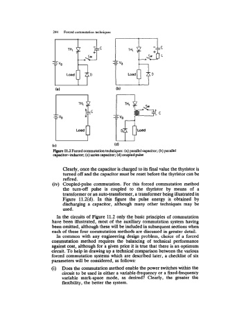
Flgurc 11.2 Forced commutation techniques: (a) parallel capacitor; (b) parallel
capacitor-inductor; (c) series capacitor; (d) coupled pulse
Clearly, once the capacitor is charged to its final value the thyristor is
turned off and the capacitor must be reset before the thyristor can be
refired.
(iv) Coupled-pulse commutation. For this forced commutation method
the turn-off pulse is coupled to the thyristor by means of a
transformer or an auto-transformer, a transformer being illustrated in
Figure 11.2(d). In this figure the pulse energy is obtained by
discharging a capacitor, although many other techniques may be
used.
In the circuits of Figure 11.2 only the basic principles of commutation
have been illustrated, most of the auxiliary commutation system having
been omitted, although these will be included in subsequent sections when
each of these four commutation methods are discussed in greater detail.
In common with any engineering design problem, choice of a forced
commutation method requires the balancing of technical performance
against cost, although for a given price it is true that there is an optimum
circuit. To help in drawing up a technical comparison between the various
forced commutation systems which are described later, a checklist of six
parameters will be considered, as follows:
(i) Does the commutation method enable the power switches within the
circuit to be used in either a variable-frequency or a fixed-frequency
variable mark-space mode, as desired? Clearly, the greater the
flexibility, the better the system.