
Page 249 - Power Electronics Handbook
P. 249
The cycloinverter 239
step-up cycloconverter, or more commonly a cycloinverter. The important
difference between this and the more popular inverter, described in
Chapter 13, is that there is no d.c. line in the cycloconverter, the power
being converted directly from an input a.c. at one frequency to an output at
a higher one. The turn-off energy required by the conducting thyristors
must again be derived from the high-frequency side, i.e. the load, in this
instance. If the load has a leading power factor then this requirement will
be met, and if it has a lagging power factor then a capacitor must be
connected across it to artificially reproduce this condition.
tit
TH, TH, TH, TH, TH, TH,
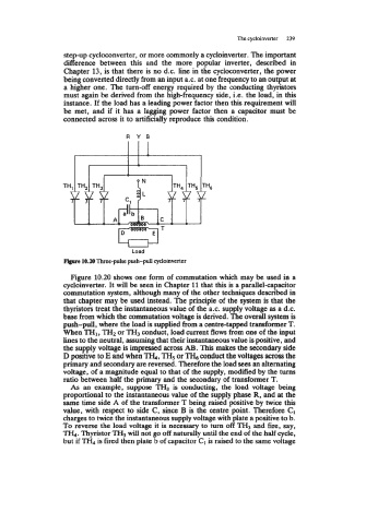
10.20 Three-pulse push-pull cycloinverter
Figure 10.20 shows one form of commutation which may be used in a
cycloinverter. It will be seen in Chapter 11 that this is a parallelcapacitor
commutation system, although many of the other techniques described in
that chapter may be used instead. The principle of the system is that the
thyristors treat the instantaneous value of the a.c. supply voltage as a d.c.
base from which the commutation voltage is derived. The overall system is
push-pull, where the load is supplied from a centre-tapped transformer T.
When TH1, TH2 or TH3 conduct, load current flows from one of the input
lines to the neutral, assuming that their instantaneous value is positive, and
the supply voltage is impressed across AB. This makes the secondary side
D positive to E and when TH,, TH5 or TH, conduct the voltages across the
primary and secondary are reversed. Therefore the load sees an alternating
voltage, of a magnitude equal to that of the supply, modified by the turns
ratio between half the primary and the secondary of transformer T.
As an example, suppose TH3 is conducting, the load voltage being
proportional to the instantaneous value of the supply phase R, and at the
same time side A of the transformer T being raised positive by twice this
value, with respect to side C, since B is the centre point. Therefore C1
charges to twice the instantaneous supply voltage with plate a positive to b.
To reverse the load voltage it is necessary to turn off TH3 and fire, say,
TH.,. Thyristor TH3 will not go off naturally until the end of the half cycle,
but if TH4 is fired then plate b of capacitor C1 is raised to the same voltage