
Page 245 - Power Electronics Handbook
P. 245
-
Phasecontrolled cycloconverters 235
Phase 1
n
Phase
2
v
Phase 3
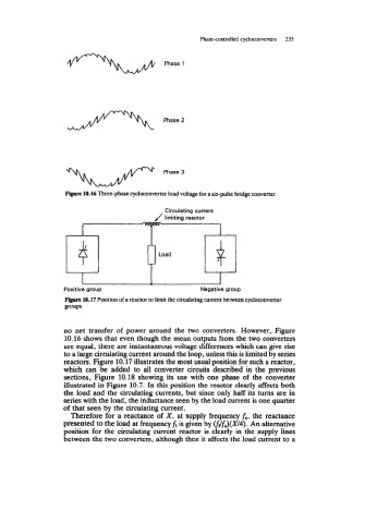
Figure 10.16 Three-phase cycloconverter load voltage for a six-pulse bridge converter
Positive group Negative group
FIgurc 10.17 Position of a reactor to limit the circulating current between cycloconverter
PUPS
no net transfer of power around the two converters. However, Figure
10.16 shows that even though the mean outputs from the two converters
are equal, there are instantaneous voltage differences which can give rise
to a large circulating current around the loop, unless this is limited by series
reactors. Figure 10.17 illustrates the most usual position for such a reactor,
which can be added to all converter circuits described in the previous
sections, Figure 10.18 showing its use with one phase of the converter
illustrated in Figure 10.7. In this position the reactor clearly affects both
the load and the circulating currents, but since only half its turns are in
series with the load, the inductance seen by the load current is one quarter
of that seen by the circulating current.
Therefore for a reactance of X, at supply frequency fs, the reactance
presented to the load at frequencyfi is given by (fifs)(X/4). An alternative
position for the circulating current reactor is clearly in the supply lines
between the two converters, although then it affects the load current to a