
Page 243 - Power Electronics Handbook
P. 243
Envelope cycloconverters 233
transformer. From this figure it can be seen that the load voltage will have
a very high harmonic content and this can be reduced, as in Figure
10.13(b), by using a six-pulse converter. Once again the load voltage
follows the envelope of the various phase voltages and the output voltage is
almost rectangular in shape.
Since most cycloconverters have an input transformer, it is possible to
vary the ratio of their secondaries with respect to one another. For
instance, Figure 10.13(c) shows the output voltage obtained from a system
in which phase 1 has 33%, phases 2 and 6 have 73%, and phases 2 and 5
have 97% of the voltage of that of phase 4. The operation is once again of
the envelope type, where the load voltage commutates naturally from
phase to phase, so that it is always equal to that of the most positive phase.
This system gives an output with a good approximation to a sine wave and
was widely used io the 1920s and 1930s for traction applications, to provide
a stable 16.66Hz (20- for 6OHz supplies) voltage.
It can be seen from the above discussions that the half cycle output
waveform from envelope cycloconverters is identical to that obtained if the
thyristors were all replaced by diodes, so that conduction begins at the
commencement of the supply cycle. The function of the thyristor is now
purely to ensure that one of the converter groups is switched off when the
other group is conducting, so that there is no short-circuit path across the
supply.
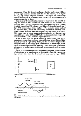
Figure 10.14 illustrates an alternative form of envelope cycloconverter,
often referred to as asynchronous to distinguish it from the synchronous
type of envelope converter described with reference to Figure 10.13.
Positive group Negative group
(a)
Output load
voltage
(b)
1e.M One form of asynchronous envelope cycloconvener: (a) circuit arrangement; (b)
waveforms