
Page 238 - Power Electronics Handbook
P. 238
228 Direct ax. frequency converters
converters and Figure 10.5 shows a functionally identically circuit made
from two push-pull converters. The operation of this system is represented
by the previous load waveforms if TH3 and TI-&, for the bridge are replaced
by TH1 for push-pull, TH4 and TH5 for the bridge are replaced by TH2 for
push-pull, TH, and TH2 for bridge are replaced by TH, for push-pull, and
TH1 and TH, for bridge are replaced by TH3 for push-pull. TH1 and TH2
therefore correspond to the positive group and TH,, TH, to the negative
one. In common with rectifier converters, it can be seen that although
push-pull systems use half as many thyristors as a bridge circuit, these have
now to be rated at twice the load voltage.
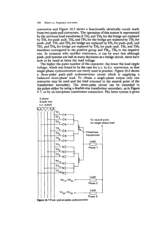
The higher the pulse number of the converter, the lower the load ripple
voltage, which was found to be the case for a.c. to d.c. converters, so that
single-phase cycloconverters are rarely used in practice. Figure 10.6 shows
a three-pulse push-pull cycloconverter circuit which is supplying a
balanced three-phase load. To obtain a single-phase output only one
converter may be used and the load returned to the neutral point of the
transformer secondary. The three-pulse circuit can be extended to
six pulses either by using a double-star transformer secondary, as in Figure
9.7, or by an interphase transformer connection. The latter system is given
3 phase
double star
a.c. supply
To neutral point
for single phase load
. Interphase
transformer
Load
---c3-
Phase 1
Load
TH13-THz,
Phase 2
Load
THZ5-TH38 #--u
Phase 3
Figure 10.7 Push-pull six-pulse cycloconverter