
Page 235 - Power Electronics Handbook
P. 235
Cycloconverter principles 225
delay angle is limited by the requirement of ensuring that the negative
voltage is of sufficient duration to turn off a thyristor during a
commutation period.
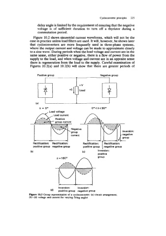
Figure 10.2 shows sinusoidal current waveforms, which will not be the
case in practice unless load filters are used. It will, however, be shown later
that cycloconverters are more frequently used in three-phase systems,
where the output current and voltage can be made to approximate closely
to a sine wave. During periods when the load voltage and current are in the
same sense, either positive or negative, there is a flow of power from the
supply to the load, and when voltage and current are in an opposite sense
there is regeneration from the load to the supply. Careful examination of
Figures 10.2(a) and 10.2(b) will show that there are greater periods of
Positive group Negative group
-
Load
Load current
- Inversion:
Positive
group current
Negative
group
negative
current
-I--
Rectification: Rectification: Rectification: Rectification: group
positive group negative group positive group negative group
Inversion:
(b) (C)
positive
a=18Oo group
Inversion: Inversion:
(d) positive group negative group
Figure 103 Group representation of a cycloconverter: (a) circuit arrangement;
(b)-(d) voltage and current for varying firing angles