
Page 236 - Power Electronics Handbook
P. 236
226 Direct a.c. frequency converters
input power than there are of regeneration. Net regeneration can be
obtained by a rearrangement of firing pulses, as shown in Figure 10.2(c).
The problem of regeneration is identical to that encountered in usual
phase-control circuits, as discussed in Chapter 9, so a cycloconverter can be
readily made to control the flow of power in either direction, which is one
of its greatest assets.
The operation of the cycloconverter can be explained more clearly with
reference to its group diagram, as shown in Figure 10.3(a), the load voltage
waveforms being given in Figures 10.3(b) to 10.3(d) for converter delay
angles varying from 0" to 180". The function of the two converters is seen to
change from full rectification to full inversion, in varying stages. It is clear
that each converter must therefore be able to rectify and invert within a
half cycle. Since only one converter cames the load current at any instant,
it is possible to fire only this system when required, but it will be seen later
that there are often advantages to firing both converters simultaneously,
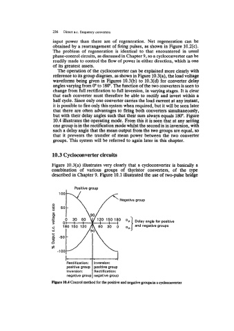
but with their delay angles such that their sum always equals 180". Figure
10.4 illustrates the operating mode. From this it is seen that at any setting
one group is in the rectification mode whilst the second is in inversion, with
such a delay angle that the mean output from the two groups are equal, so
that it prevents the transfer of mean power between the two converter
groups. This system will be referred to again later in this chapter.
10.3 Cycloconverter circuits
Figure 10.3(a) illustrates very clearly that a cycloconverter is basically a
combination of various groups of thyristor converters, of the type
described in Chapter 9. Figure 10.1 illustrated the use of two-pulse bridge
Positive group
Delay angle for positive
and negative groups
Rectification: Inversion:
positive group positive group
Inversion: Rectification:
negative group negative group