
Page 234 - Power Electronics Handbook
P. 234
224 Direct ax. frequency converters
Line voltoar
8 3 4 3 4 7 E 7
1 6 5 6 5 2 I 2
7 8 7 4 3 4 3 4 3 0 7 0 1
(cJ I 2 5 6 5 6 5 6 1 2 I 2
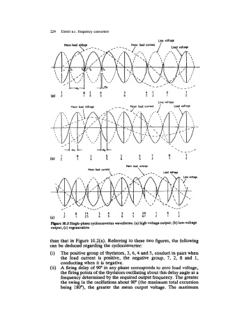
Figure 10.2 Single-phase cycloconvener waveforms: (a) high-voltage output; (b) low-voltage
output; (c) regeneration
than that in Figure 10.2(a). Referring to these two figures, the following
can be deduced regarding the cycloconverter:
(i) The positive group of thyristors, 3, 6, 4 and 5, conduct in pairs when
the load current is positive, the negative group, 7, 2, 8 and 1,
conducting when it is negative.
(ii) A firing delay of 90'' in any phase corresponds to zero load voltage,
the firing points of the thyristors oscillating about this delay angle at a
frequency determined by the required output frequency. The greater
the swing in the oscillations about 90" (the maximum total excursion
being lW), the greater the mean output voltage. The maximum