
Page 229 - Power Electronics Handbook
P. 229
Voltage multiplication circuits 219
charges through diode D1 to the peak supply voltage with plate 1 positive.
On the next half cycle, when line A is positive, the voltage on C1 adds to
the peak of the input supply to pump twice the peak supply voltage onto
capacitor G, so that the voltage across CD on no load is twice the peak of
the input supply, this reducing slightly on load. It is this pumping action
which gives this circuit its name, although it is also known as a common
terminal voltage doubler, because one side of the load and the input a.c.
supply share a common terminal. The output ripple frequency is equal to
that of the supply, so that this circuit needs a larger value of capacitor for
the same regulation, compared to the symmetrical voltage-doubler circuit.
+ c
1 Load
L.---J
B
) IC1
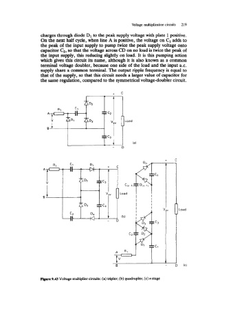
F@wc 9.43 Voltage multiplier circuits: (a) tripler; (b) quadrupler; (c) n stage