
Page 226 - Power Electronics Handbook
P. 226
216 Phase-controlled rectification and inversion
which is defined as the ratio of the harmonic to the d.c. voltage, is given by
equation (9.23).
vh = 2 v~ (9.20)
n = 1,2,3. . .
VkS = v:v(a) + vf (9.21)
vh = [vas - V&U)]’’~ (9.22)
(9.23)
The harmonic factor can be evaluated for several different circuits, for
example considering the bi-directional bridge rectifier circuit of Figure 9.4,
where V is the r.m.s. supply voltage, the r.m.s output voltage is given by
equation (9.24) and, since the d.c. voltage for zero delay angle is given by
equation (9.25) and the d.c. voltage for finite firing angle delay of (Y is
given by equation (9.6), the harmonic factor reduces to that of equation
(9.26).
n+a M
V,, = [i (J(2) Vsin 9)’d9] (9.24)
(9.25)
M
Hf = [$ - COS’CY] (9.26)
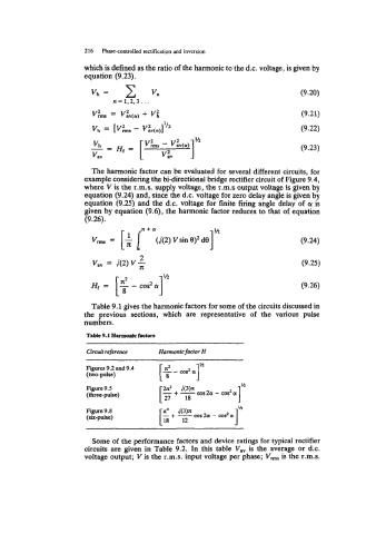
Table 9.1 gives the harmonic factors for some of the circuits discussed in
the previous sections, which are representative of the various pulse
numbers.
Tabk 9.1 H8rmonk factom
Circuit reference Harmonic factor H
[ $ - cos2 &I ~~
L4
9.2
Figures (two-pulse) and 9.4
Figure 9.5 -+- J(3)x I”
2x2
(three-pulse) [ 27 18 20 - ms2
Figure 9.8 3”
(six-pulse)
Some of the performance factors and device ratings for typical rectifier
circuits are given in Table 9.2. In this table Vav is the average or d.c.
voltage output; V is the r.m.s. input voltage per phase; V,, is the r.m.s.