
Page 228 - Power Electronics Handbook
P. 228
21 8 Phase-controlled rectification and inversion
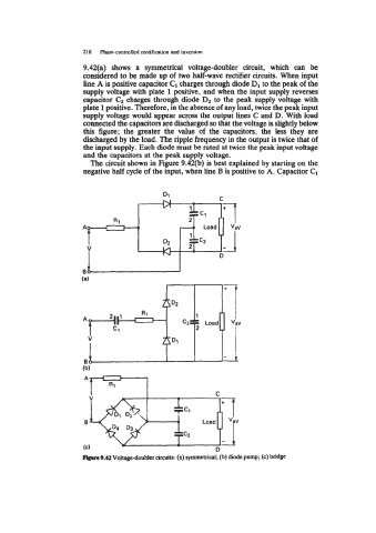
9.42(a) shows a symmetrical voltage-doubler circuit, which can be
considered to be made up of two half-wave rectifier circuits. When input
line A is positive capacitor C1 charges through diode D1 to the peak of the
supply voltage with plate 1 positive, and when the input supply reverses
capacitor charges through diode D2 to the peak supply voltage with
plate 1 positive. Therefore, in the absence of any load, twice the peak input
supply voltage would appear across the output lines C and D. With load
connected the capacitors are discharged so that the voltage is slightly below
this figure; the greater the value of the capacitors, the less they are
discharged by the load. The ripple frequency in the output is twice that of
the input supply. Each diode must be rated at twice the peak input voltage
and the capacitors at the peak supply voltage.
The circuit shown in Figure 9.42(b) is best explained by starting on the
negative half cycle of the input, when line B is positive to A. Capacitor C1
-9.42 Voltage-doubler circuits: (a) symmetrical; (b) diode pump; (c) bridge