
Page 227 - Power Electronics Handbook
P. 227
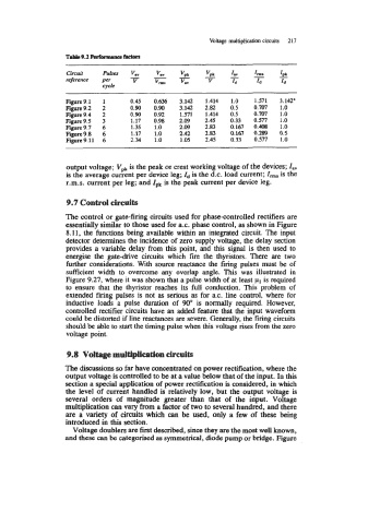
Voltage multiplication circuits   217

                   Table 9.2 Marmuice Mora

                   circuit    PUlSeS   -
                                     V.V
                   reference   Per    V
                              cycle
                   Figure 9.1        0.45   0.636   3.142   1.414   1.0   1.571   3.142.
                   Figure 9.2        0.90   0.90   3.142   2.82   0.5   0.707   1.0
                   Figure 9.4        0.90   0.92   1.571   1.414   0.5   0.707   1.0
                   Figure 9.5        1.17   0.98   2.09   2.45   0.33   0.577   1.0
                   Figure 9.7        1.35   1.0    2.09   2.83   0.167   0.408   1  .o
                   Figure 9.8        1.17   1.0    2.42   2.83   0.167   0.289   0.5
                   Figure 9.11       2.34   1  .o   1.05   2.45   0.33   0.577   1.0


                   output voltage; vpk is the peak or crest working voltage of the devices; I,,
                   is the average current per device leg; Id is the d.c. load current; I,,,,,  is the
                   r.m.s. current per leg; and zpk is the peak current per device leg.

                    9.7 Control circuits

                   The control or gate-firing circuits used for phase-controlled rectifiers are
                   essentially similar to those used for a.c. phase control, as shown in Figure
                   8.11,  the functions being available within an integrated circuit. The input
                   detector determines the incidence of  zero supply voltage, the delay section
                   provides a variable delay from this point, and  this signal is then used  to
                   energise  the  gate-drive circuits which  fire the  thyristors. There  are  two
                   further considerations. With  source reactance the firing pulses must be  of
                   sufficient  width  to  overcome any  overlap angle.  This  was  illustrated  in
                   Figure 9.27, where it was shown that a pulse width of at least pl is required
                   to  ensure that  the  thyristor reaches  its full  conduction. This problem  of
                   extended firng pulses is not  as serious as for a.c. line control, where for
                   inductive  loads  a  pulse  duration  of  90" is  normally  required.  However,
                   controlled rectifier circuits have an added feature that the input waveform
                   could be distorted if line reactances are severe. Generally, the firing circuits
                   should be able to start the timing pulse when this voltage rises from the zero
                   voltage point.

                    9.8  Voltage multiplication circuits

                   The discussions so far have concentrated on power rectification, where the
                   output voltage is controlled to be at a value below that of the input. Io this
                   section a special application of  power rectification is considered, in which
                   the level of  current handled is relatively low,  but  the output voltage is
                   several  orders  of  magnitude  greater  than  that  of  the  input.  Voltage
                   multiplication can vary from a factor of two to several hundred, and there
                   are a  variety of  circuits which  can be  used,  only  a few of  these being
                   introduced in this section.
                     Voltage doublers are first described, since they are the most well known,
                   and these can be categorised as symmetrical, diode pump or bridge. Figure