
Page 233 - Power Electronics Handbook
P. 233
Cycloconverter principles 223
properties of cycloconverters. In the following sections the various
cycloconverter circuit arrangements, both single- and three-phase, are
introduced and this is followed by a description of envelope-type
cycloconverters and a performance analysis of phasecontrolled conver-
ters.
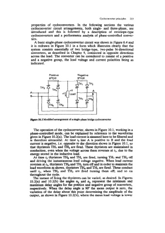
A basic single-phase cycloconverter circuit was shown in Figure 6.4 and
it is redrawn in Figure 10.1 in a form which illustrates clearly that the
system consists essentially of two bridge-type, two-pulse bi-directional
converters, as described in Chapter 9, connected in opposite directions
across the load. The converter can be considered to consist of a positive
and a negative group, the load voltage and current polarities being as
indicated.
Positive Negative
group group
r J
A
B
pbvc 10.1 Modified arrangement of a single-phase bridge cycloconverter
The operation of the cycloconverter, shown in Figure 10.1, working in a
phaseantrolled mode, can be explained by reference to the waveforms
given in Figure 10.2(a). The load current is assumed here to be filtered and
is therefore sinusoidal. At time to line A is positive to B and the load
current is negative, i.e. opposite to the direction shown in Figure 10.1, so
that thyristors TH7 and TH2 are fired. These thyristors are maintained in
conduction, even when the voltage across them reverses at tl, due to the
energy stored in the inductive load.
At time fz thyristors TH, and THl are fired, turning TH7 and TH2 off
and driving the instantaneous load voltage negative. When load current
reverses at t3, thyristors l& and TH1 turn off and in order to maintain the
load waveform as shown, thyristors TH,j and TH3 are fired. These conduct
until r4, when TH, and TH5 are fired turning them off, and so on
throughout the cycle.
The instant of firing the thyristors can be varied, as desired. In Figures
10.2(a) and 10.2(b) the angles (yp and a,, represent the minimum and
maximum delay angles for the positive and negative group of converters,
respectively. When the delay angle is 90" the mean output is zero, the
variation of the delay about this point determining the amplitude of the
output, as shown in Figure 10.2(b), where the mean load voltage is lower