
Page 244 - Power Electronics Handbook
P. 244
234 Direct a.c. frequency converters
Figure 10.14(a) shows that the circuit is essentially the usual arrangement
of a cycloconverter with the addition of an induction regulator, which is fed
from the three-phase supply, in series with the load. The output voltage
from the six-pulse converter is as illustrated in Figure 10.13(b) and to this is
added the induction regulator output, so as to give the resultant load
voltage of the form shown in Figure 10.14(b). Once again, the
approximation to a sine wave is very close.
Envelope cycloconverters are incapable of variable-frequency operation
and, since the converter thyristors operate like diodes during any
half cycle, they cannot regenerate load current back to the supply. For this
to occur the firing angle on the thyristors would need to be delayed beyond
the start of a cycle, as in normal a.c. to d.c. converters. Therefore envelope
cycloconverters are incapable of handling inductive loads since they cannot
absorb its reactive power. For stable operation it is now necessary to
connect a capacitor in parallel across the load, to raise its overall power
factor. This disadvantage is not met with in phase-controlled converters,
where the firing angle can be shifted readily to meet any required direction
of load current flow.
10.5 Phase-controlled cycloconverters
The operation of a phase-controlled cycloconverter has already been
described with reference to a single-phase system, as in Figure 10.2. It is
seen that the load frequency can be controlled by the oscillation frequency
of the firing point about 90". The load voltage amplitude is governed by the
extent of this oscillation about the mean firing point and the converter can
be readily switched from rectification to inversion by regulating the firing
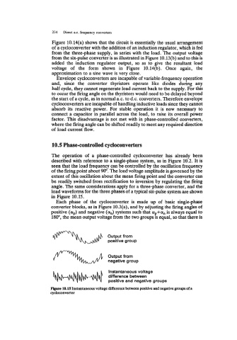
angle. The same considerations apply for a three-phase converter, and the
load waveforms for the three phases of a typical six-pulse system are shown
in Figure 10.15.
Each phase of the cycloconverter is made up of basic single-phase
converter blocks, as in Figure 10.3(a), and by adjusting the firing angles of
positive (t+) and negative (a,,) systems such that ap+a,, is always equal to
180", the mean output voltage from the two groups is equal, so that there is
Output from
positive group
Output from
negative group
Instantaneous voltage
difference between
positive and negative groups
-re 10.15 Instantaneous voltage difference between positive and negative groups of a
cycloconverter