
Page 257 - Power Electronics Handbook
P. 257
Parallel-capacitor commutation 247
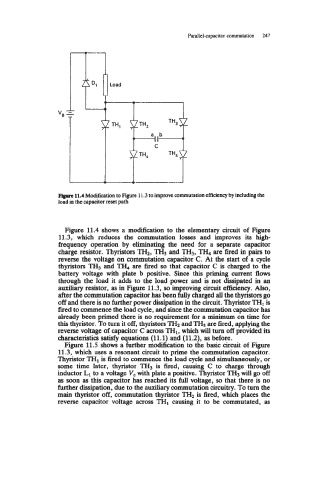
Figure 11.4 Modification to Figure 11.3 to improve cornmutation efficiency by including the
load in the capacitor reset path
Figure 11.4 shows a modification to the elementary circuit of Figure
11.3, which reduces the commutation losses and improves its high-
frequency operation by eliminating the need for a separate capacitor
charge resistor. Thyristors TH2, THs and TH3, TH, are fired in pairs to
reverse the voltage on commutation capacitor C. At the start of a cycle
thyristors TH3 and TI€, are fired so that capacitor C is charged to the
battery voltage with plate b positive. Since this priming current flows
through the load it adds to the load power and is not dissipated in an
auxiliary resistor, as in Figure 11.3, so improving circuit efficiency. Also,
after the commutation capacitor has been fully charged all the thyristors go
off and there is no further power dissipation in the circuit. Thyristor THI is
fired to commence the load cycle, and since the commutation capacitor has
already been primed there is no requirement for a minimum on time for
this thyristor. To turn it off, thyristors TH2 and TH5 are fired, applying the
reverse voltage of capacitor C across TH1, which will turn off provided its
characteristics satisfy equations (11.1) and (11.2), as before.
Figure 11.5 shows a further modification to the basic circuit of Figure
11.3, which uses a resonant circuit to prime the commutation capacitor.
Thyristor TH1 is fired to commence the load cycle and simultaneously, or
some time later, thyristor TH3 is fired, causing C to charge through
inductor Ll to a voltage V, with plate a positive. Thyristor TH3 will go off
as soon as this capacitor has reached its full voltage, so that there is no
further dissipation, due to the auxiliary commutation circuitry. To turn the
main thyristor off, commutation thyristor TH2 is fired, which places the
reverse capacitor voltage across TH1 causing it to be commutated, as