
Page 265 - Power Electronics Handbook
P. 265
Series capacitor commutation 255
when THl turns off. The capacitor voltage is given by equation
(1 1.7).
(iv) A commutation failure prevents the circuit from re-attempting
commutation.
(v) The rating of thyristor TH1 is increased by the resonance of C through
L1-
(vi) There is no low-impedance short-circuit current path across the
supply.
11.5 series capacitor commutation
The basic series capacitor commutation circuit is shown in Figure 11.2(c),
where a commutation capacitor is connected in series With the load.
Assume that initially this capacitor is discharged when thyristor TH1 is
fired to start the load cycle. The capacitor now commences to charge
towards the supply voltage, and when the current through the thyristor
falls below its holding current the device will turn off. Clearly, this
elementary circuit is capable of a single pulse only and some mechanism
must be used to reset the capacitor voltage before the main thyristor can be
refired.
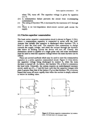
There are several methods which may be used to reset the commutation
capacitor in a series capacitor commutated circuit. Figure ll.ll(a) shows
the capacitor voltage being discharged by resistor R1 when the main
thyristor is turned off. As before, this thyristor THl is fired to commence
the load cycle. Generally, the system requires an underdamped resonant
circuit, made up of L1, C and the load, such that the capacitor charges with
plate b greater than that of the battery (V,) so that thyristor THI is reverse
biased and turns off more rapidly than when the current is simply reduced
to below its holding value.
Load
r- V,
Load
Figure 11.11 Series capacitor commutation: (a) resistor
reset; (b) load reset; (c) resonant reset