
Page 269 - Power Electronics Handbook
P. 269
Coupled-pulse commutation 259
thyristor TH1 is fired to commence the load cycles and when it is required
to commutate its gate turn-off switch, TH2, is turned on. Capacitor C
discharges into transformer T1, reverse biasing TH1 and it will turn off
providing the reverse voltage is maintained for a time in excess of its
turn-off time. C will resonate with the inductance of T1 and when this has
been completed gate turn-off switch TH2 is turned off by its gate control,
enabling C to recharge with its b plate positive, ready for another
commutation cycle.
The circuit of Figure 11.12 can be analysed as follows:
(i) It can operate in a variable-frequency or a variable mark-space mode.
(ii) The minimum on time can be made very small, since commutation
can start soon after the main thyristor has been fired. The minimum
off time is determined by the resonant time for C to charge via L1 and
is given by equation (11.9). Therefore the chopper is capable of a
wide output voltage range.
(iii) The commutation voltage is not appreciably increased by the load
current , assuming low transformer inductance.
(iv) If commutation is not successful and TH1 does not turn off when TH2
is fired, then when TH2 is turned off the capacitor will recharge so
that commutation will be re-attempted on the following cycle.
(v) The current rating of the main thyristor is not increased by the reset
action of the commutation circuit.
(vi) A low-impedance current path does not exist across the d.c. supply,
in the advent of a commutation failure, assuming that gate turn-off
switch TH2 has not failed to turn off.
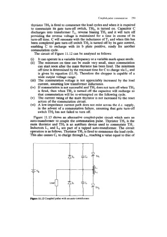
Figure 11.13 shows an alternative coupled-pulse circuit which uses an
auto-transformer to couple the commutation pulse. Thyristor TH1 is the
main thyristor and TH2 is an auxiliary device used to commutate THI.
Inductors LI and b are part of a tapped auto-transformer. The circuit
operation is as follows. Thyristor THI is fired to commence the load cycle.
This also causes C1 to charge through L1, reaching a value equal to that of
Figure 11.13 Coupled pulse with an auto-transformer