
Page 274 - Power Electronics Handbook
P. 274
264 D.C. to d.c. converters
(C)
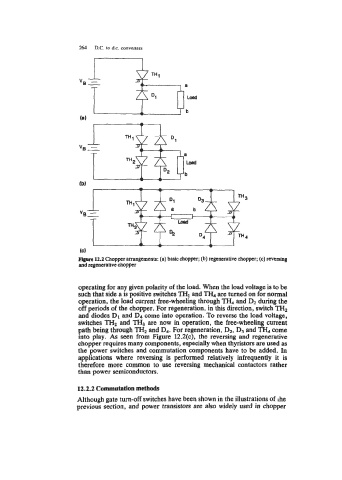
Flopre 12.2 Chopper arrangements: (a) basic chopper; (b) regenerative chopper; (c) reversing
and regenerative chopper
operating for any given polarity of the load. When the load voltage is to be
such that side a is positive switches "HI and TH, are turned on for normal
operation, the load current free-wheeling through TH4 and Dz during the
off periods of the chopper. For regeneration, in this direction, switch TH2
and diodes D, and D4 come into operation. To reverse the load voltage,
switches TH2 and TH, are now in operation, the free-wheeling current
path being through TH, and D4. For regeneration, Dz, D3 and TH, come
into play. As seen from Figure 12.2(c), the reversing and regenerative
chopper requires many components, especially when thyristors are used as
the power switches and commutation components have to be added. In
applications where reversing is performed relatively infrequently it is
therefore more common to use reversing mechanical contactors rather
than power semiconductors.
12.2.2 Commutation methods
Although gate turn-off switches have been shown in the illustrations of ihe
previous section, and power transistors are also widely used in chopper