
Page 276 - Power Electronics Handbook
P. 276
266 D.C. to d.c. converters
-
b
zz C
TH, a
TH,
tl 41
L
I
Load
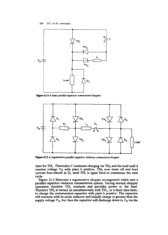
12.5 A regenerative parallel capacitor-inductor commutated chopper
time for TH1. Thereafter C continues charging via TH, and the load until it
reaches voltage VB with plate b positive. TH, now turns off and load
current free-wheels in D1 until THI is again fired to commence the next
cycle.
Figure 12.5 illustrates a regenerative chopper arrangement which uses a
parallel capacitor-inductor commutation system. During normal chopper
operation thyristor TH3 conducts and provides power to the load.
Thyristor TH, is turned on simultaneously with TH,, or a short time later,
to charge the commutation capacitor with plate b positive. The capacitor
will resonate with its series inductor and initially charge to greater than the
supply voltage V,, but then the capacitor will discharge down to V, via the