
Page 279 - Power Electronics Handbook
P. 279
D.C. to d.c. converter circuits 269
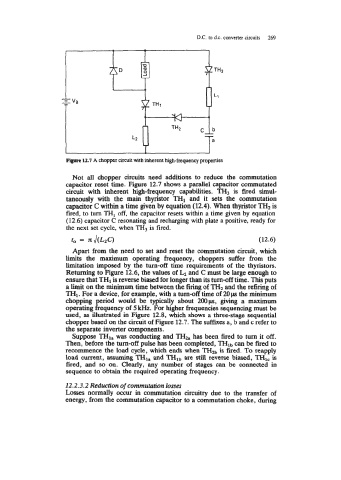
F@ue 12.7 A chopper Circuit with inherent high-frequency properties
Not all chopper circuits need additions to reduce the commutation
capacitor reset time. Figure 12.7 shows a parallel capacitor commutated
circuit with inherent high-frequency capabilities. TH3 is fired simul-
taneously with the main thyristor TH1 and it sets the commutation
capacitor C within a time given by equation (12.4). When thyristor TH2 is
fired, to turn TH, off, the capacitor resets within a time given by equation
(12.6) capacitor C resonating and recharging with plate a positive, ready for
the next set cycle, when TH3 is fired.
to = JdL*c) (12.6)
Apart from the need to set and reset the commutation circuit, which
limits the maximum operating frequency, choppers suffer from the
limitation imposed by the turn-off time requirements of the thyristors.
Retuming to Figure 12.6, the values of LZ and C must be large enough to
ensure that TH1 is reverse biased for longer than its turn-off time. This puts
a limit on the minimum time between the firing of TH2 and the refiring of
TH1. For a device, for example, with a turn-off time of 20p the minimum
chopping period would be typically about 200ps, giving a maximum
operating frequency of 5 kHz. For higher frequencies sequencing must be
used, as illustrated in Figure 12.8, which shows a three-stage sequential
chopper based on the circuit of Figure 12.7. The suffixes a, b and c refer to
the separate inverter components.
Suppose TH1, was conducting and THza has been fired to turn it off.
Then, before the tum-off pulse has been completed, THlb can be fired to
recommence the load cycle, which ends when THzb is fired. To reapply
load current, assuming TH1, and THlb are still reverse biased, TH1, is
fired, and so on. Clearly, any number of stages can be connected in
sequence to obtain the required operating frequency.
12.2.3.2 Reduction of commutation losses
Losses normally occur in commutation circuitry due to the transfer of
energy, from the commutation capacitor to a commutation choke, during