
Page 282 - Power Electronics Handbook
P. 282
272 D.C. to d.c. converters
thyristor TH2 would turn off at this point and the load current would
free-wheel in D1, but due to the presence of this inductor, there is energy
(EST) stored in it, given by equation (12.9).
EST = MLsIi (12.9)
This energy causes TH2 to remain on, the voltage on C increasing as the
current through it decreases, the difference between this and the load
free-wheeling through D1.
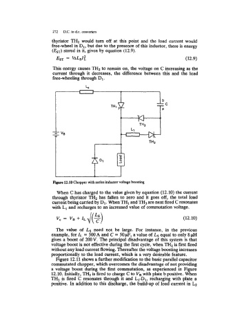
12.10 Chopper with series inductor voltage boosting
When C has charged to the value given by equation (12.10) the current
through thyristor TH2 has fallen to zero and it goes off, the total load
current being carried by D1. When TH1 and TH3 are next fired C resonates
with L1 and recharges to an increased value of commutation voltage.
v, = v, + ZLJ(2) (12.10)
The value of Ls need not be large. For instance, in the previous
example, for Zt = 500 A and C = 50 p, a value of Ls equal to only 8 pH
gives a boost of 200V. The principal disadvantage of this system is that
voltage boost is not effective during the first cycle, when TH2 is first fired
without any load current flowing. Thereafter the voltage boosting increases
proportionally to the load current, which is a very desirable feature.
Figure 12.11 shows a further modification to the basic parallel capacitor
commutated chopper, which overcomes the disadvantage of not providing
a voltage boost during the first commutation, as experienced in Figure
12.10. Initially, TH2 is fired to charge C to V, with plate b positive. When
THI is fired C resonates through it and L1-D1, recharging with plate a
positive. In addition to this discharge, the build-up of load current in