
Page 280 - Power Electronics Handbook
P. 280
270 D.C. to d.c. converters
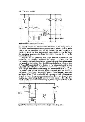
Figure 12.8 Three-stage sequential chopper
the turn-off process and the subsequent dissipation of the energy stored in
the choke. The commutation loss is proportional to the load current, which
determines the capacitor size for any voltage and the frequency of
operation. There is a fixed watts loss per commutation, so that the higher
the operating frequency, the larger the energy loss and the lower the
system efficiency.
Choppers do not generally have high inherent cornmutation loss
problems. For instance, referring to Figures 12.4 and 12.7, the
commutation energy is interchanged between choke and capacitor during
the turn-off period, so that there should theoretically be no efficiency loss.
In Figure 12.7, assuming C to be charged to V,, with plate b positive, then
when TH2 is fired TH1 turns off. C now resonates with and discharges to
zero voltage. The commutation energy has transferred from C to k, but
the commutation interval proceeds beyond this point, with the transfer of
energy back from to C, so that the capacitor recharges to Vpk with plate
a positive. When TH3 is next fired C will resonate through the supply and
L1 and be reset, giving zero commutation loss. However, it can be seen
that the capacitor voltage builds up over several cycles, to the value V
which may be several times the supply VB depending on the losses in tgl
Figure 12.9 Commutation energy recovery in the chopper circuit of Figure 12.7