
Page 285 - Power Electronics Handbook
P. 285
Design of chopper circuits 275
The presence of any harmonic, and its magnitude, is therefore
determined by the duty cycle of the output pulse, and is shown plotted in
Figure 12.13, which also illustrates the variation of the mean voltage, as
given by equation (12.1). This plot shows that harmonics are present at all
times except when the chopper switch is continuously open (k = 0) or
continuously closed (k = l), the harmonic with the largest magnitude being
that at the chopping frequency, as expected.
12.4 Design of chopper circuits
This section provides an analysis of chopper circuits to enable their design
characteristics to be obtained. Initially, the commutation components will
be ignored, so that the results are equally applicable to any form of
switching control, for example those using transistors or mechanical
switches, but later the effects of commutation, as needed for thyristor
circuits, on a typical chopper are considered.
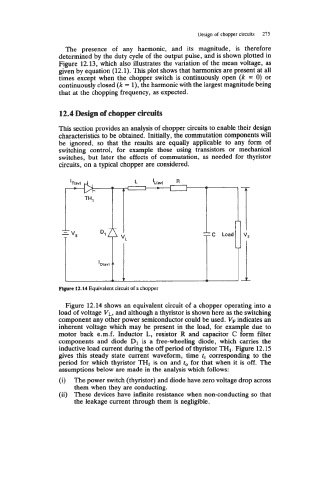
Figure 12.14 Equivalent circuit of a chopper
Figure 12.14 shows an equivalent circuit of a chopper operating into a
load of voltage V,, and although a thyristor is shown here as the switching
component any other power semiconductor could be used. VF indicates an
inherent voltage which may be present in the load, for example due to
motor back e.m.f. Inductor L, resistor R and capacitor C form filter
components and diode D1 is a free-wheeling diode, which carries the
inductive load current during the off period of thyristor TH1. Figure 12.15
gives this steady state current waveform, time fc corresponding to the
period for which thyristor TH1 is on and f,, for that when it is off. The
assumptions below are made in the analysis which follows:
(i) The power switch (thyristor) and diode have zero voltage drop across
them when they are conducting.
(ii) These devices have infinite resistance when non-conducting so that
the leakage current through them is negligible.