
Page 292 - Power Electronics Handbook
P. 292
282 D.C. to d.c. converters
12.6 Chopper control circuits
The basic control circuit for a chopper consists of a mechanism for turning
on the main switching semiconductor at the start of a cycle and of turning
off the device when the cycle is to be terminated. If this main switch is a
thyristor it can be commutated by firing an auxiliary thyristor. Usually
there are two main applications for choppers, to provide a stabilised power
supply and to control the speed of a d.c. motor by varying the voltage
across it. Both these applications require some form of voltage sensing, in
order to keep the load voltage constant under varying current or supply
voltage fluctuations. In addition, the current to the load is sensed and
current limit applied if this exceeds a predetermined value.
Variable
frequency 4
generator generator control
1
Voltage detect
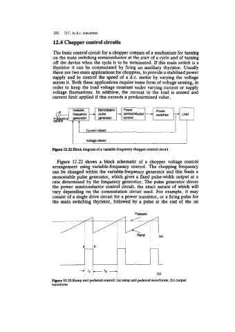
12.22 Block diagram of a variable-frequency chopper control circuit
Figure 12.22 shows a block schematic of a chopper voltage control
arrangement using variable-frequency control. The chopping frequency
can be changed within the variable-frequency generator and this feeds a
monostable pulse generator, which gives a fixed pulse-width output at a
rate determined by the frequency generator. The pulse generator drives
the power semiconductor control circuit, the exact nature of which will
vary depending on the commutation circuit used. For example, it may
consist of a single drive circuit for a power transistor, or a firing pulse for
the main switching thyristor, followed by a pulse at the end of the on
-