
Page 93 - Power Electronics Handbook
P. 93
86 Power semiconductor control components
Electrostatic shielding reduces the voltage transfer through the inter-
winding capacitances. It is needed to prevent the transfer of transient
voltages or high-frequency noise from the power input circuit to the
secondary circuit. The shield is usually a grounded metallic plate between
the primary and secondary windings. Electromagnetic shielding is used to
attenuate the magnetic field which leaks from the magnetic circuit of the
transformer and induces voltages in adjoining circuits. Placing a magnetic
shield around the transformer is not usually very effective, since most of
the stray lines of flux from the transformer would be perpendicular to the
shield and would pass through it. A better solution is to separate the
transformer and adjoining sensitive circuits and to orientate them to
minimise pick-up. The adjoining circuits can also be shielded by layers of
thin, high-permeability material, which are usually interleaved with layers
of non-magnetic material, such as copper.
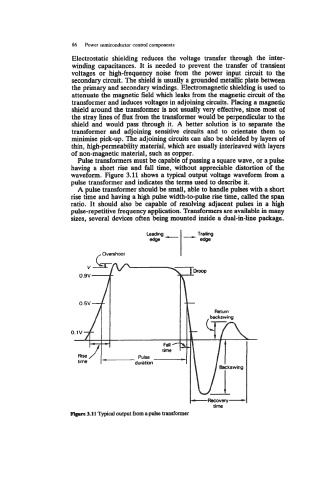
Pulse transformers must be capable of passing a square wave, or a pulse
having a short rise and fall time, without appreciable distortion of the
waveform. Figure 3.11 shows a typical output voltage waveform from a
pulse transformer and indicates the terms used to describe it.
A pulse transformer should be small, able to handle pulses with a short
rise time and having a high pulse width-to-pulse rise time, called the span
ratio. It should also be capable of resolving adjacent pulses in a high
pulse-repetitive frequency application. Transformers are available in many
sizes, several devices often being mounted inside a dual-in-line package.
Trailing
/overshoot I
0.1v n
I1 1 I I.
Fell
time
Rise R ,l.w
time
time
Figure 3.11 Typical output from a pulse transformer