
Page 150 - Power Quality in Electrical Systems
P. 150
132 Chapter Nine
Alternate CB
line
To load
CB
Diesel
Line CB M G
engine
Motor starter
Flywheel Eddy current
clutch
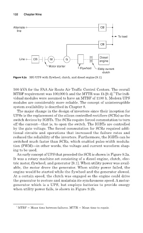
Figure 9.2a MG UPS with flywheel, clutch, and diesel engine [9.1].
500 kVA for the FAA Air Route Air Traffic Control Centers. The overall
1
MTBF requirement was 100,000 h and the MTTR was 1h [9.4]. The indi-
vidual modules were assumed to have an MTBF of 1100 h. Modern UPS
modules are considerably more reliable. The concept of uninterruptible
system availability is described in Chapter 8.
The major change in the design of inverters since their inception for
UPSs is the replacement of the silicon controlled rectifiers (SCRs) as the
switch devices by IGBTs. The SCRs require forced commutation to turn
off the current—that is, to open the switch. The IGBTs are controlled
by the gate voltage. The forced commutation for SCRs required addi-
tional circuits and operations that increased the failure rates and
reduced the reliability of the inverters. Furthermore, the IGBTs can be
switched much faster than SCRs, which enabled pulse-width modula-
tion (PWM)—in other words, the voltage and current waveform shap-
ing to be used.
An early concept of UPS that preceded the SCR is shown in Figure 9.2a.
It was a rotary machine set consisting of a diesel engine, clutch, elec-
tric motor, flywheel, and generator [9.1]. When utility power was avail-
able, the motor drove the generator. When utility power failed, the
engine would be started while the flywheel and the generator slowed.
At a certain speed, the clutch was engaged so the engine could drive
the generator to restore and maintain its synchronous speed. A motor-
generator which is a UPS, but employs batteries to provide energy
when utility power fails, is shown in Figure 9.2b.
1
MTBF Mean time between failures. MTTR Mean time to repair.