
Page 148 - Power Quality in Electrical Systems
P. 148
130 Chapter Nine
Normal utiliity source
Main
CB
Main bus
Non-emerg. UPS input
CB CB
To non-emergency Battery
load charger
Battery
Bypass circuit
Inverter
Bypass static UPS output
switch CB
Bypass
CB
Emerg. AC bus
To emergency AC load
(a)
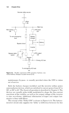
Figure 9.1a Double conversion UPS: inverter; battery; con-
verter-battery charger; by-pass circuit [9.1].
maintenance by-pass—is usually provided when the UPS is taken
out of service.
Both the battery charger (rectifier) and the inverter utilize power
semiconductor devices, which are switched to convert power from AC to
DC, or DC to AC. The theory of operation is described in Chapter 5. The
devices are usually pulse-width modulated to shape the line-current
waveform of the rectifier, as well as the output voltage of the inverter
to sine waveforms. Additional elimination of input and output har-
monics is done with filters.
The concept of the “Delta UPS” is shown in Figure 9.1b. The battery-
inverter circuit only supplies the “delta” or difference between the line