
Page 204 - Practical Control Engineering a Guide for Engineers, Managers, and Practitioners
P. 204
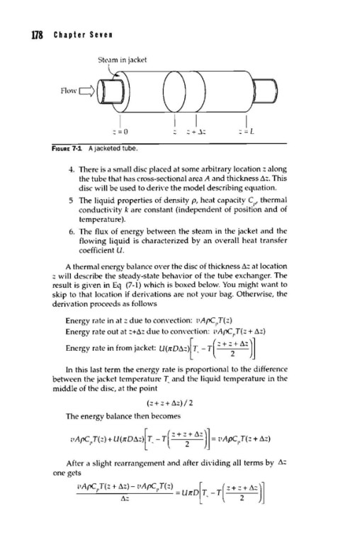
178   C  h  a  p  t  e  r  S  e  v  e  n


                        Steam in jacket


               Flow Q


                             I                             I
                            :=0              :  + ~:     :  = L
             fiGURE 7-1  A jacketed tube.

                 4.  There is a small disc placed at some arbitrary location z along
                    the tube that has cross-sectional area A and thickness ~z. This
                    disc will be used to deri,·e the model describing equation.
                 5  The liquid properties of density p, heat capacity c,,J  thermal
                    conducti,·ity k are constant (independent of position and of
                    temperature).
                 6.  The  flux  of energy between the steam in the jacket and the
                    flowing  liquid  is  characterized by an O\'erall  heat  transfer
                    coefficient U.

                A thermal energy balance O\'er the disc of thickness~::: at location
             :::  will describe the steady-state behavior of the tube exchanger. The
             result is gi\'en in Eq  (7-1)  which is boxed below. You  might want to
             skip to that location  if deri\'ations are not your bag. Otherwise, the
             derivation proceeds as follows

                Energy rate in at z due to convection:  1.'A{>C ,T(z)
                                                    1
                Energy rate out at:::+~::: due to convection:  1.'Af>C,.T(z + ~z)
                        t  ·  f
                                              [
                                 ·  k  t
                 E  nergy ra  em  rom JaC  e :  U(1rO~:::) T,  - T  ( ::: + ::: + ~z  )]
                                                       2
                 In this last term the energy rate is proportional to the difference
             between the jacket temperature T..  and the liquid temperature in the
             middle of the disc, at the point
                                    (::: + z + ~z)  I 2
                The energy balance then becomes


                 After a slight rearrangement and after di,·iding all terms by  ~:::
             one gets
                   <•ArC1,T(z + "':~- PArC1,T(z) = UlrD[T, _ T( z + : + t.:  )]
                                                          2