
Page 70 - Practical Control Engineering a Guide for Engineers, Managers, and Practitioners
P. 70
Basic Concepts in Process Analysis 45
and to manipulate U in proportion to the error, that is,
U = ke = k(S- Y) (3-17)
where k is the proportional control gain.
Before proceeding, let's think about Eq. (3-17) with reference to
the water tank. Assume that initially Y is equal to the set pointS so
that e is initially zero. Also, assume that the nominal initial values
have been subtracted from all of the quantities, so Y, S, e, and U are
initially zero. If S is stepped up, then e would become nonzero and
positive. This would mean that U would increase, assuming that k is
positive. An increase in U means more flow into the tank and the
level Y should rise. Okay, at least the control algorithm has the correct
signs and moves the controller output in the right direction.
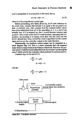
Schematically, this feedback control system can be presented as a
block diagram (Fig. 3-3). This is a classic schematic that will reappear
many times in many forms in the balance of this book. Note how the pro-
cess output Y is fed back and subtracted from the set pointS producing the
errorE which is fed to the controller which produces the process input U.
Combine Eqs. (3-15) and (3-17)
dY
fdt+Y=gU
U=k(S- Y)
and get
dY
f-+Y=gk(S- Y)
dt
S (Set point)
U (Controller output/
process input valve position)
Proportional
controller
Process
Y (Process output (Tank) U (Process input)
height) L..-----r---.J
D (Disturbances)------'
F1auRE 3-3 A feedback controller.