
Page 465 - Practical Design Ships and Floating Structures
P. 465
440
The following series of calculations was carried out for the new design:
Draught condition Reynolds number Propeller
loaded 7.96* 10 (model scale) no
loaded 3.73*10 (full scale) no
loaded 7.96* 10 (model scale) Yes
empty 8.68* 10 (model scale) no
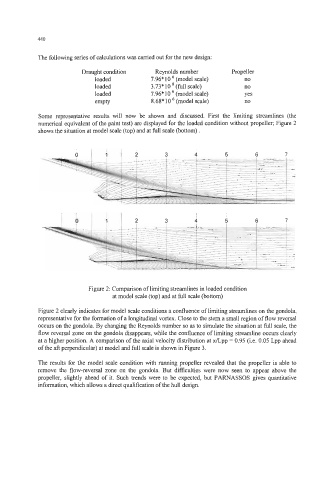
Some representative results will now be shown and discussed. First the limiting streamlines (the
numerical equivalent of the paint test) are displayed for the loaded condition without propeller; Figure 2
shows the situation at model scale (top) and at full scale (bottom) .
I I I
3 4 5 6 7
Figure 2: Comparison of limiting streamlines in loaded condition
at model scale (top) and at full scale (bottom)
Figure 2 clearly indicates for model scale conditions a confluence of limiting streamlines on the gondola,
representative for the formation of a longitudinal vortex. Close to the stem a small region of flow reversal
occurs on the gondola. By changing the Reynolds number so as to simulate the situation at full scale, the
flow reversal zone on the gondola disappears, while the confluence of limiting streamline occurs clearly
at a higher position. A comparison of the axial velocity distribution at x/Lpp = 0.95 (i.e. 0.05 Lpp ahead
of the aft perpendicular) at model and full scale is shown in Figure 3.
The results for the model scale condition with running propeller revealed that the propeller is able to
remove the flow-reversal zone on the gondola. But difficulties were now seen to appear above the
propeller, slightly ahead of it. Such trends were to be expected, but PARNASSOS gives quantitative
information, which allows a direct qualification of the hull design.