
Page 467 - Practical Design Ships and Floating Structures
P. 467
442
persisted and was brought closer to the propeller. So it was decided to reject the hull modification.
Because there was no time left for further exercises the hull design was accepted as maybe not perfect
but certainly good enough to guarantee an acceptable inflow to the propeller.
5 PROPELLER DESIGN
For the propeller design two sets of data concerning the wake field in loaded and empty condition were
delivered by the PARNASSOS code: the wake field plots of axial, radial and tangential velocity
components (as normally delivered after conduction of a wake field model test), and, in addition, the
pressure distribution over the propeller plane. Because the nominal wake field for both the model scale
and full scale situation was provided, as well as the flow field with active propeller, the propeller
designer got in fact more information than usual. He assessed the wake fields as "quite normal", which
ensured the yard that the job was well done for this single-screw full-block aft body.
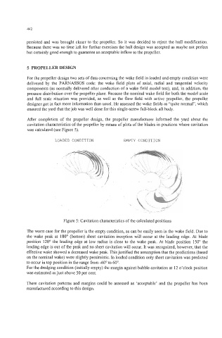
After completion of the propeller design, the propeller manufacturer informed the yard about the
cavitation characteristics of the propeller by means of plots of the blades in positions where cavitation
was calculated (see Figure 5).
LOADED CONDITION EMPTY CONDITION
Figure 5: Cavitation characteristics of the calculated positions
The worst case for the propeller is the empty condition, as can be easily seen in the wake field. Due to
the wake peak at 180" (bottom) sheet cavitation inception will occur at the leading edge. At blade
position 120" the leading edge at low radius is close to the wake peak. At blade position 150" the
leading edge is out of the peak and no sheet cavitation will occur. It was recognized, however, that the
effective wake showed a decreased wake peak. This justified the assumption that the predictions (based
on the nominal wake) were slightly pessimistic. In loaded condition only sheet cavitation was predicted
to occur in top position in the range from -60" to 60".
For the dredging condition (initially empty) the margin against bubble cavitation at 12 o'clock position
was estimated as just above 50 per cent.
These cavitation patterns and margins could be assessed as 'acceptable' and the propeller has been
manufactured according to this design.