
Page 112 - Practical Design Ships and Floating Structures
P. 112
81
TABLE 2
PRINCIPAL DIMENSIONS OF CATA 111 2.5 WL
2.0 WL
1.0 WL
Ease Line
1.OEL t1.06L
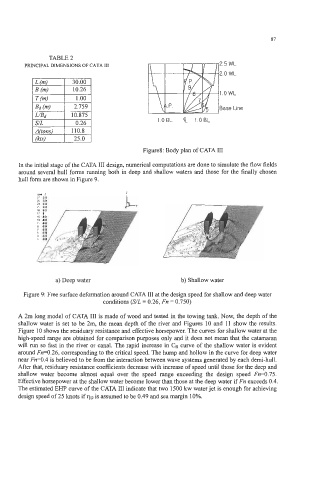
Figures: Body plan of CATA I11
In the initial stage of the CATA I11 design, numerical computations are done to simulate the flow fields
around several hull forms running both in deep and shallow waters and those for the finally chosen
hull form are shown in Figure 9.
z
Lnd I
I7 OM I
IS OM
13 003
11 001
a) Deep water b) Shallow water
Figure 9: Free surface deformation around CATA I11 at the design speed for shallow and deep water
conditions (S/L = 0.26, Fn = 0.750)
A 2m long model of CATA I11 is made of wood and tested in the towing tank. Now, the depth of the
shallow water is set to be 2m, the mean depth of the river and Figures 10 and 11 show the results.
Figure 10 shows the residuary resistance and effective horsepower. The curves for shallow water at the
high-speed range are obtained for comparison purposes only and it does not mean that the catamaran
will run so fast in the river or canal. The rapid increase in CR curve of the shallow water is evident
around Fn=0.26, corresponding to the critical speed. The hump and hollow in the curve for deep water
near Fn=0.4 is believed to be from the interaction between wave systems generated by each demi-hull.
After that, residuary resistance coefficients decrease with increase of speed until those for the deep and
shallow water become almost equal over the speed range exceeding the design speed Fn=0.75.
Effective horsepower at the shallow water become lower than those at the deep water if Fn exceeds 0.4.
The estimated EHP curve of the CATA I11 indicate that two 1500 kw water jet is enough for achieving
design speed of 25 knots if q~ is assumed to be 0.49 and sea margin 10%.