
Page 109 - Practical Design Ships and Floating Structures
P. 109
84
the purpose. The water is relatively calm for the most part of the routes but is shallow with extreme
tidal differences reaching almost lometers in some places. The size of the canal gates and bridges
across the Han River Mer restricts the size of the ships operable in the routes. With careful
investigation on the natural condition of the routes and various economic aspects, principal dimensions
of a catamaran carrying 300 passengers at relatively high-speed ranges have been selected. [Chun &
Lee (1999)l Total of three hull forms of ,the catamaran have been studied and their resistance
characteristics are investigated experimentally and numerically.
2 HULL FORM DEVELOPMENTS
2.1 CATA I& ZZ
The initial hull form, CATA I has been derived from a project done by a group of undergraduate
students. In the project, a 1/1OOth scale model of a 165m long wave-piercing catamaran with a center
bow and for operation in ‘ICN - main Incheon’ route had been manufactured and tested by the group
in the model basin of the Inha University. The ship may not be appropriate for the general use in
Incheon area mainly because her draft is too large and too fast to operate in the river and the canal. But
it can be a good starting point, however, especially in calibrating numerical and experimental tools and
procedures for predicting catamaran performances operating in the shallow water. [Millward (1984)]
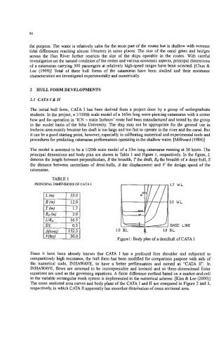
The model is assumed to be a lL?Oth scale model of a 33m long catamaran running at 30 knots. The
principal dimensions and body plan are shown in Table 1 and Figure 1, respectively. In the figure, L
denotes the length between perpendiculars, B the breadth, T the draft, &the breadth of a demi-hull, S
the distance between centerlines of demi-hulls, A the displacement and V the design speed of the
catamaran.
TABLE I
PRINCIPAL DIMENSIONS OF C :ATA I
, INE
Figure1 : Body plan of a demihull of CATA I
Since it have been already known that CATA I has a profound fore shoulder and subjected to
comparatively high resistance, the hull form has been modified for comparison purpose with aids of
the numerical code, INHAWAVE, to have a better performances and named as “CATA II”. In
INHAWAVE, flows are assumed to be incompressible and inviscid and so three-dimensional Euler
equations are used as the governing equations. A finite difference method based on a marker-and-cell
in the variable rectangular mesh system is implemented in the numerical scheme. [Kim & Lee (2000)l
The cross sectional area curves and body plans of the CATA I and I1 are compared in Figure 2 and 3,
respectively, in which CATA I1 apparently has smoother distribution of cross sectional area.