
Page 105 - Practical Design Ships and Floating Structures
P. 105
80
4.2 Propeller dm&n
Propeller performance calculations were conducted using MARM's computer programs TIPVCI and
DESPRO, together with knowledge from individually and systematically tested propellers, such as the
B-series. Parameters that were varied were the diameter, blade area, blade number and pitch
(distribution). When the inception speed of tip vortex cavitation was accepted as the determining
criterion, a 7 bladed propeller with a pitch of about 1.3 was found to be favourable from cavitation
point of view. It was found that a diameter of 2.75 m should be applied. Although the propeller tips
touch the boundary layer of the hull, the lower rotation rate in this case is beneficial.
4.3 Manoeuvring and Dynamic Tracking
The manoeuvring tests were conducted to verify the conclusions drawn during the desk study and to
obtain more accurate information regarding the manoeuvring characteristics. As was predicted in the
preliminary analysis, the ship complied easily with all manoeuvring requirements. Although not
applicable to this ship, the manoeuvring characteristics also complied with the draft IMO Resolution
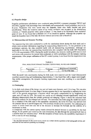
A.75 1 (1 8) requirements (1993). During the model test phase, also dynamic tracking (DT) tests in wind
and waves with correction for current were conducted, to verify compliance with the dynamic tracking
requirements. After proper calibration of the DT control system, it was found that the requirement was
met:
2.3 m 8" I 3.1 %ofthetime
With the model tests uncertainties during the desk study were removed and the vessel demonstrated
excellent manoeuvring and trackkeeping characteristics. It was found that with a single-screw/single-
flap rudder arrangement, the dynamic tracking requirements were met, resulting in a cost-efficient
solution.
4.4 Seakeeping
In the desk study phase of the design, two anti roll tanks were foreseen, each 2.4 m long. This was also
the configuration tested. In a later stage it became apparent that it was impossible to maintain the lower
ART in the general arrangement, a decision which was partly compensated for by lengthening the
upper anti roll tank by 25%. The model test results on roll damping showed significantly lower roll
damping characteristics than the initially predicted roll damping. Figure 3 shows the corrected final
downtime analysis for the enlarged anti roll tank. The correction was made using the model test results.
By a variation of the GM value in the operability calculations, the lower KG limit was derived from
the criterion that at 45 and 60 degrees the 17% downtime should not be exceeded. The seakeeping test
results in severe head seas also led to the decision to increase the bulwark and the addition of a
breakwater on deck.
A comparison with the current survey vessels showed the desired increase in operability for the final
design, for the greater part caused by the main dimensions, but also through the optimised hull form as
it resulted from the variation study'. With the exception of beam waves, the operability requirement of
83% is met for all wave headings.
' The calculated downtime for the current survey vessels was verified with the experience of the hydrographic service, and
confirmed for head and bow quartering wave headings