
Page 103 - Practical Design Ships and Floating Structures
P. 103
78
quartering waves, which would therefore receive special attention in the seakeeping experimental
program.
3.2 Hull form optimkation andpropeller verification
The mission profile of this vessel was rather complicated. Good propulsive efficiency is required while
at the same time the wake field of the ship has to allow for the design of a low noise signature
propeller. Above all, excellent steering ability was demanded.
The concept with wing thrusters was believed promising, as the wing propulsors might be sufficient to
achieve the survey speed, whereas the central propeller needs to deliver the thrust for normal transition
speed. For full speed all three propulsors would be used, filling the gap between 9 and 13 knots by the
thruster power enabling direct diesel drives for all shafts. Unfortunately, it was found that the power
for the wing thrusters was too little to fill the gap. The single pod arrangement was dismissed because
of the high associated costs and minimal advantage of applying a single pod over a single propeller-
rudder configuration. Finally, the twin screw exposed shaft arrangement failed in efficiency compared
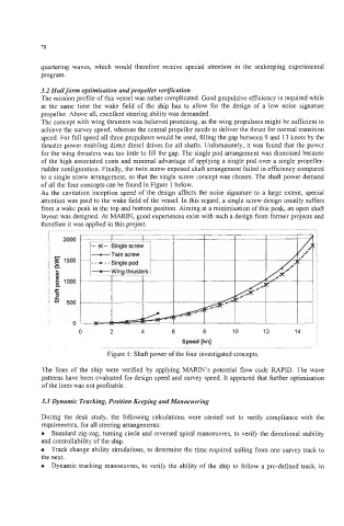
to a single screw arrangement, so that the single screw concept was chosen. The shaft power demand
of all the four concepts can be found in Figure 1 below.
As the cavitation inception speed of the design affects the noise signature to a large extent, special
attention was paid to the wake field of the vessel. In this regard, a single screw design usually suffers
from a wake peak in the top and bottom position. Aiming at a minimisation of this peak, an open shaft
layout was designed. At MARIN, good experiences exist with such a design from former projects and
therefore it was applied in this project.
___ -
0 2 4 6 a 10 12 14
Speed [kn]
Figure 1 : Shaft power of the four investigated concepts.
The lines of the ship were verified by applying MARIN’S potential flow code RAPID. The wave
patterns have been evaluated for design speed and survey speed. It appeared that further optimisation
of the lines was not profitable.
3.3 Dynamic Tracking, Position Keeping and Manoeuvring
During the desk study, the following calculations were carried out to verify compliance with the
requirements, for all steering arrangements:
Standard zig-zag, turning circle and reversed spiral manoeuvres, to verify the directional stability
and controllability of the ship.
Track change ability simulations, to determine the time required sailing from one survey track to
the next.
Dynamic tracking manoeuvres, to verify the ability of the ship to follow a pre-defined track, in