
Page 126 - Practical Design Ships and Floating Structures
P. 126
101
corresponding to the largest slope angle, which is regarded as the most dangerous situation for
structure. It is assumed that T is initial trim angle, yo is initial track angle, V, is horizontal velocity,
V, is vertical velocity, eis maximum wave slope, with consideration of waves, the corresponded
effective initid parameters can be get:
effective trim angle: T .= - 0 effective horizontal velocity: V,,=V,+/-V,,
effective track angle: ye= e +tg-'(Vfl,) effective vertical velocity: V,=V+os e +(V,+/-V,)sin e
the largest wave slope: e =tg-'( h/ wave velocity: v,,,== 1.2s In
where 'h' is wave height and A is wave length, so method for impact load in calm water can be used for
that in waves with effective parameters mentioned above.
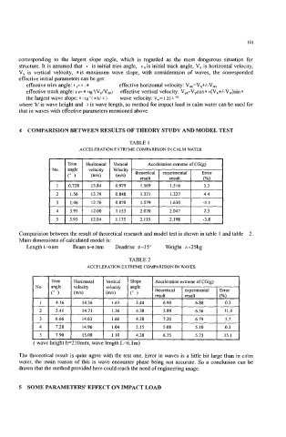
4 COMPARISION BETWEEN RESULTS OF THEORY STUDY AND MODEL TEST
TABLE 1
ACCELERATION EXTREME COMPARlSlON IN CALM WATER
Comparision between the result of theoretical research and model test is shown in table 1 and table 2.
Main dimensions of calculated model is:
Length L=o.8m Beam b=o.28m Deadrise B =15" Weight ~=25kg
TABLE 2
ACCELERATION EXTREME COMPARISION IN WAVES
-.
I I Trim I Horizontal I Vertical I Slope I Acceleration extreme of CGk) 1
No. angle velocity velocity angie theoretical experimental Error
(m/s)
(" ) WS) result result (%)
I 4.16 14.36 1.63 3.44 6.90 6.88 0.3
2 5.41 14.71 1.36 4.38 5.89 6.56 11.4
3 6.66 14.63 1.60 4.38 7.20 6.79 5.7
4 7.28 14.96 1.04 5.15 5.08 5.10 0.3
5 7.90 15.08 1.10 4.38 6.75 5.73 15.1
5 SOME PARAMETERS' EFFECT ON IMPACT LOAD