
Page 134 - Practical Design Ships and Floating Structures
P. 134
109
resistance components shall not be discussed in this paper due to limited space. In this study, the
optimum buoyancy/lift ratio is found to be 45 : 55, which is very close to the initial estimation of 40 :
60.
5 HYDROFOIL SYSTEM DESIGN
Hydrofoil system for large-size foil catamaran ships are mainly consisted of forward foil, aft foil, side
struts which connect foil to ship hull and one or two center struts. Basically, hydrofoil system should
be designed to satisfy the following two conditions in normal sailing :
- the system should produce as much lift as the amount designated by the selected buoyancyllift
ratio
- forward and aft foils should properly share the lift to maintain the desired dynamic trim
In fact, it is very difficult to design the optimum hydrofoil system for foil catamaran ships. First of all,
accurate estimation of the effect of free-surface on the hydrodynamic characteristics is very difficult.
Interactions between ship hull and foil system, and between forward and afl foils are very complicated.
Due to such complicated physical phenomena, no proper method has been practically existed to predict
the performance characteristics or to determine characteristics of a foil system. Along the course of
extended research works on the super-high-speed foil-catamaran ships, however, the authors have
prepared a practically accurate method to predict the hydrodynamic characteristics or to determine
main characteristics of a hydrofoil system operated in the vicinity of free-surface[lO - 121. This
method has been actively utilized in the actual design of various foil systems. In this study, the
hydrofoil system has been designed to produce the lift equivalent to 55% of ship's design displacement
and to maintain the even keel state during normal sailing from the stationary state of 0.5 degree trim by
stem.
6 PREDICTION OF THE TRIAL PERFORMANCE
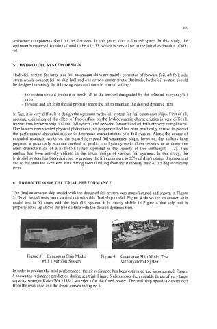
The final catamaran ship model with the designed foil system was manufactured and shown in Figure
3. Detail model tests were carried out with this final ship model. Figure 4 shows the catamaran ship
model test in 60 knots with the hydrofoil system. It is clearly visible in Figure 4 that ship hull is
properly lifted up above the free-surface with the desired dynamic trim.
I
Figure 3: Catamaran Ship Model Figure 4: Catamaran Ship Model Test
with Hydrofoil System with Hydrofoil System
In order to predict the trial performance, the air resistance has been estimated and incorporated. Figure
5 shows the resistance prediction during sea trial. Figure 5 also shows the available thrust of very large
capacity waterjet(KaMeWa 25530 waterjet ) for the fixed power. The trial ship speed is determined
from the resistance and the thrust curves in Figure 5..