
Page 139 - Practical Design Ships and Floating Structures
P. 139
114
energy efficiency from economical and environmental considerations necessitates more rigorous effort
for reducing the frictional resistance.
Among several mcthods for frictional drag reduction, reducing the effective wetted surface area by
covering some portion of the hull surface with air film is conceptually easy to understand [Bushnell &
Hefner (1990)l. These air films can be generated through a natural intrusion of the air into the bottom
of the ship, but frequently formed more effectively by an intentional introduction of the air near the
step formed under the hull bottom. The wake of this step provides spatially fixed circulating flow
region behind the step. If air is supplied inside of this circulating region, water is displaced gradually
by air behind the step and eventually a single air cavity of nearly steady state can be formed [Knapp et
al. (1970)l. When the size of this air cavity is large enough and sufficiently stable, a significant
reduction in wetted surface area can be obtained. The reduction has been reported to reach up to 20%
of the total resistance with a careful arrangement of the steps and an appropriate supply of air [Jang &
Kim (1 999)]. However, the application of same idea to the reduction of frictional resistance of a real
ship requires more thorough understanding on the similarity relation.
In the present work, the effect of the step on the cavity formation is studied experimentally with the
geometrically similar models equipped with air supplying devices and backward-facing steps on the
bottom. In the first stage, the role of the key parameters, such as the step heights and the flow rates of
air at various advancing speeds of the models are examined. And then, scaling laws governing the
cavity area and the flow rate of air is sought. And then, the extrapolation procedure of the total
resistance is studied with two-dimensional and three-dimensional estimation methods. In order to
complete the study, a small test boat is constructed and the trials are underway.
2 RESISTANCE REDUCTION OF GEOMERICALLY SIMILAR MODEL SHIPS
2.1 Geometrically Similar Models
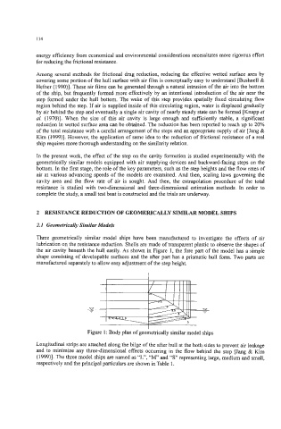
Three geometrically similar model ships have been manufactured to investigate the effects of air
lubrication on the resistance reduction. Shells are made of transparent plastic to observe the shapes of
the air cavity beneath the hull easily. As shown in Figure 1, the fore part of the model has a simple
shape consisting of developable surfaces and the after part has a prismatic hull form. Two parts are
manufactured separately to allow easy adjustment of the step height.
n
Figure 1 : Body plan of geometrically similar model ships
Longitudinal strips are attached along the bilge of the after hull at the both sides to prevent air leakage
and to minimize any threedimensional effects occurring in the flow behind the step [Jang & Kim
(1999)j. The three model ships are named as “L”, “M and “S” representing large, medium and small,
respectively and the principal particulars are shown in Table 1.