
Page 142 - Practical Design Ships and Floating Structures
P. 142
117
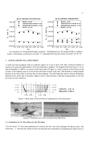
By 2D estimation method(Fmude) By 3D estimation method(Telfer)
2.OE-02 H Model L, wl Air 2.OE-02 H Model L, wl Air
A
Estimated fmm model M, wl Ail
A
Estimated from model M, wl Air
1
0
1.6E-02 -- : .- Estimated from model S, wl Air 0 6E-02 r- - 0 Estimated from model S, wl Ai
Model L, wlo Air
Model L, wlo Air
0" 0" 0
1.2E-02 '0 1.2E-02-
s
~ m : a h
K t acT ' hC,
m
c 8.OE-03 - vy 8.OE-03
0 4 . .
.
! -
.
}
c
v
4.0E-03- c, 0' 4.0E-03- . a 4 .)C,
O.OE+OO '' '' ' * a ' I ' '' I' '' ' I ' ' I ' I ' * '' I '' ' ' O.OE+OO ""llll~ll.l~l~.l~lllllllllllllY
3 APPLICATIONS TO A TEST BOAT
A small test boat equipped with an outboard engine of 15 hp is built with fiber reinforced plastic to
examine the practical applicability of the air lubrication method. The length of the test boat is 3.16 m
and the breadth is 1.089 m. As shown in the body plan of Figure 5, a step is placed at the bottom in the
vicinity of the midship and air is forced into the holes located at the step. The boat has a wedge shaped
barriers at the both sides to prevent the air from leaking. The hull form also allows natural ventilation
from the front of the step if possible. Figure 6 shows some pictures of the test running made so far and
the trials are still underway.
0.3 WL 0.3 WL
0.2 WL 0.2 WL
LENGTH 3.16 m
0.1 WL 0.1 WL
BL BL BREADTH 1.089m
Q
Figure 5: Body plan of the test boat for applications of air lubrication
Figure 6: Running tests of the test boat in the Han River
3.1 Estimation ofAir Flow Rates for the Test Boat
Tests for model "S" have been performed to estimate the flow rate of air adequate for the test boat. The
scale ratio, 1 between the model and the test boat has been selected by considering the speed limit of