
Page 154 - Practical Design Ships and Floating Structures
P. 154
129
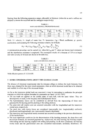
Starting from the following parameters ranges, allowable in literature: (when the m and o suffixes are
adopted to denote the main hull and the outriggers respectively):
TABLE 1
MAIN AND SIDE HULL PROPORTION RANGE
VI@ (LIB), (BIT), k+J, (LIB), (B/T), (cB),
Min 0.25 12 1.3 0.35 12 0.4 0.35
Max 0.6 18 2.5 0.65 35 2 0.7
With: V= velocity; L= length of water line; T= Immersion; CB = Block coefficient; g= gravity
acceleration; and assuming the following resistance relation, for 64 hulls:
RT=RT(Am,CBm,(T)m;Ao ,cBot( T)o,L,) (1)
Lo
B
B
A minimization procedure can be carried out, when theLmand V values are known (and constants),
and the interference resistance is neglected. The consequent results of a trimaran of 120 m in length
and with velocity of 36 knots are shown in the table two.
TABLE 2
MAIN AND SIDE HULL RESULTS
A(t) L(m) B T CB L/B B/T
Main-hull 1662.2 120 10.4 2.6 0.50 11.54 4
Outrigger 43.75 41 2.04 1.02 0.45 20.1 2
With effective power of 11534 MW.
3 SOME CONSIDERATIONS ABOUT THE GLOBAL LOADS
The absence of structural experimental data for trimaran obliges to deduce the loads formulas from
those ones obtained for the more tested catamarans, when an initial structural model has to be obtained
and verified, in a first step of the structural design.
As far as the transverse global loads are concerned, it may be interesting to synthesize the principal
concepts on which the register formulas for catamarans are based (A.B.S 1997).
The sea loads are applied on the middle plane of each hull, with the ‘same values. They are
decomposed, as usual, in the buoyancy and hydrodynamic forces.
The hydrodynamic forces can be considered as derived ftom the superposing of those ones
generated by the heaving and the pitching or the rolling motions.
The pitch and roll rotation axes are assumed coincident with the longitudinal and the transverse
central axes, respectively.
The pitch (res. roll) inertia forces are considered transversally (res. longitudinally) uniformly
distributed, and longitudinally (res. transversally) linearly distributed.
The transverse and longitudinal inertia moments are assumed according to the previous distributions
of the inertia forces.
The most significant conditions for the determination of the bending moment, the shear force and
the torsion moment, are assumed generated by, respectively, the only heaving, the heaving coupled
with rolling and the heaving coupled with rolling and pitching. In all these conditions, the heaving
inertia loads and the gravitational ones are considered transversally uniformly distributed, the