
Page 158 - Practical Design Ships and Floating Structures
P. 158
133
+ Transverse torsion moment
The M, values for a section between the impacting outrigger and the main hull, are given by :
Icase
+
AVoa, (~~fi LL Xv,,,L*m + 4v, L,L~O)
M, = (20)
(v, +2VJ L,,,[V,Li +8V,(L>, +LL)]
4 NUMERICAL EXAMPLE
In order to demonstrate the practical applicability of the 2-21 relations, a numerical example has been
developed and applied to the trimaran frigate of the figure 1.
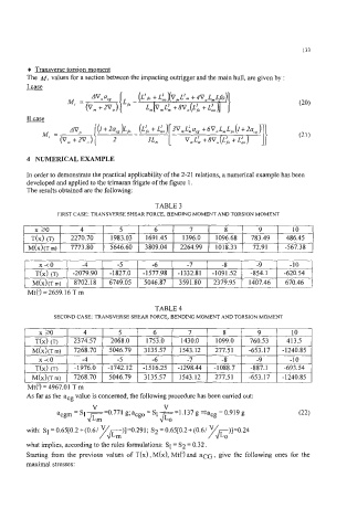
The results obtained are the following:
TABLE 3
FIRST CASE: TRANSVERSE SHEAR FORCE, BENDING MOMENT AND TORSION MOMENT
x a 4 5 6 7 8 9 10
T(x) (T) 2270.70 1983.03 1691.45 1396.0 1096.68 783.49 486.45
M(x)(T m) 7773.80 5646.60 3809.04 2264.99 1018.33 72.91 -567.38
x<o -4 -5 -6 -7 -8 -9 -10
T(x) (T) -2079.90 -1827.0 -1577.98 -1332.81 -1091.52 -854.1 -620.54
M(x)(T m) 8702.18 6749.05 5046.87 3591.80 2379.95 1407.46 670.46
TABLE 4
SECOND CASE: TRANSVERSE SHEAR FORCE, BENDING MOMENT AND TORSION MOMENT
Mt(') = 4967.01 T m
As far as the acg value is concerned, the following procedure has been carried out:
V
~-1.137g*acg=0.919g
V
acgm = Si - 4.771 g; acgo = Si -
-
JLm
with: Si = 0.65r0.2 +(0.6/7~)]=0.291; S2 = 0.65[0.2+(0.6/7~)]=0.24
Lm LO
what implies, according to the rules formulations: Si = S2 = 0.32.
Starting from the previous values of T(x) , M(x), Mt(') and aCG, give the following ones for the
maximal stresses: